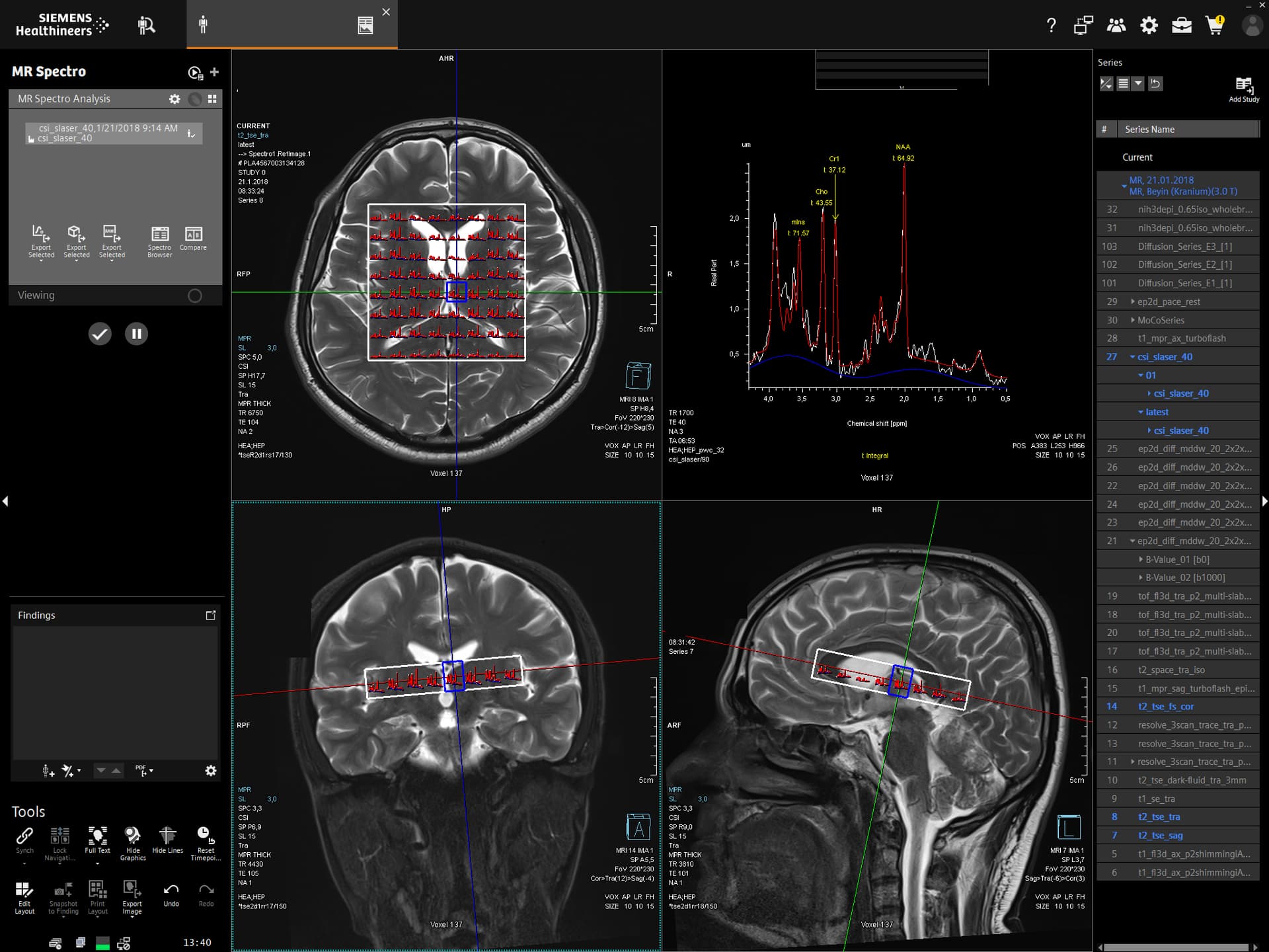
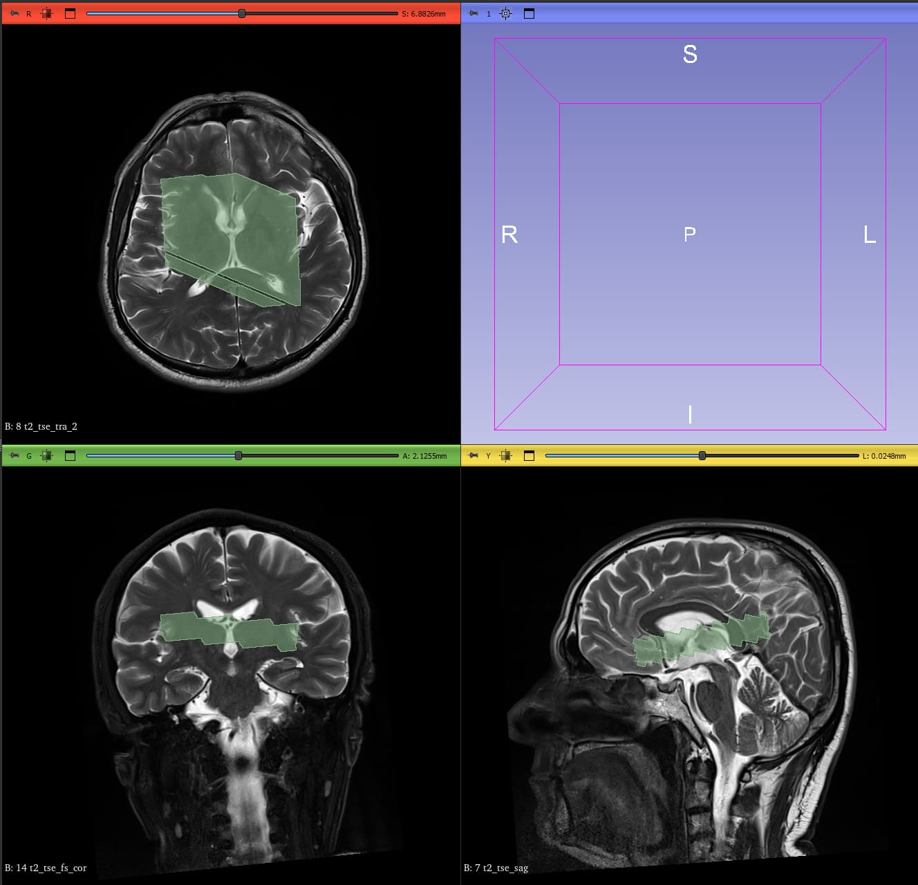
I am currently working on Siemens .rda data acquired on an XA20 system and I am trying to generate voxel masks. I have been struggling with this for a while, and because of an issue I encountered, I opened this thread where @mmikkel kindly tried to help. After re-examining both the code and the generated masks, I realized that although the voxel position is correct, the orientation is inverted in all directions (can be seen when comparing the scanner image with the generated voxel mask bellow). Initially, I thought the problem was limited to the axial plane, but it turns out that all orientations are flipped.
I tried changing the signs of the angle-related parameters (SlabOrientation) and experimented with different ways of generating the masks. I also tested the codes of several different software packages (Gannet, Osprey, FID-A, rda2nifti), but none of these approaches solved the problem. In every case, the voxel masks are produced with a mirrored or inverted orientation.
Has anyone encountered a similar problem with Siemens data before, particularly with XA20? Could this be related to a convention difference (coordinate system, handedness, or orientation definitions), or is there something obvious that I might be missing?
I am sharing both the data and my code in the attachments. Any insight or suggestions would be highly appreciated. Thank you.
There is an RDA pipeline in that and I’m fairly confident after a lot of testing that the Siemens orientation codes does the right thing, though with the caveat that I have very little xa20 data to test on.
I just downloaded and tested it. I checked the rda.py file, and the header entries seem to be compatible with my XA20 files. When I display the voxel, it appears in the correct location, but it has no orientation.
Previously i either used the RowVector and ColumnVector information to compute the orientation, as in your code, or use the SlabOrientation entries, but both approaches end up giving the same inverted angles.
Odd that there isn’t any orientation. I’ll take a look at the example data you linked. Did you definitely select the right patient orientation at scan time (I presume head first supine)?
I was not involved in the image acquisition since this is an old dataset, but I know that the patient orientation is HFS and the coordinate system is LPH+. Please feel free to check the data, and thank you for your help .
@ardacanbas1 Did you modify the .rda file at all? The software version it reports is VE - SoftwareVersion[0]: syngo MR E11. My other XA20 examples report SoftwareVersion[0]: syngo MR XA20
I didn’t change anything in the .rda file. However, it confused me because the header entries are the same as those in the XA series, as can be seen in [this (CoRegistration Error in Osprey with NIfTI) topic. I am also using the code provided by @hraum in that thread to read the header, and it works fine, except that the orientation is inverted.
Yes there is some weirdness to this file. As well as the odd SoftwareVersion, the rowvector is the negative of the SlabOrientation[2,:] vector rather than equal to it, as is the case for all my other examples (though these are limited to SVS).
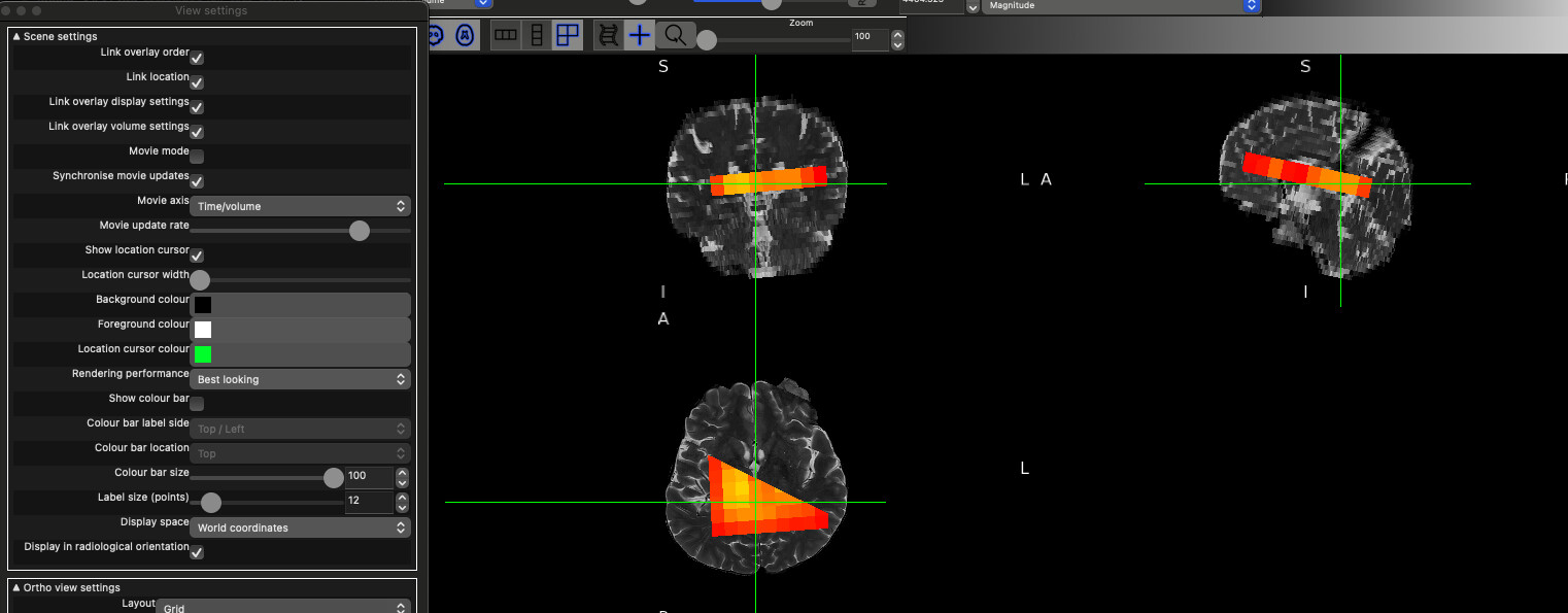
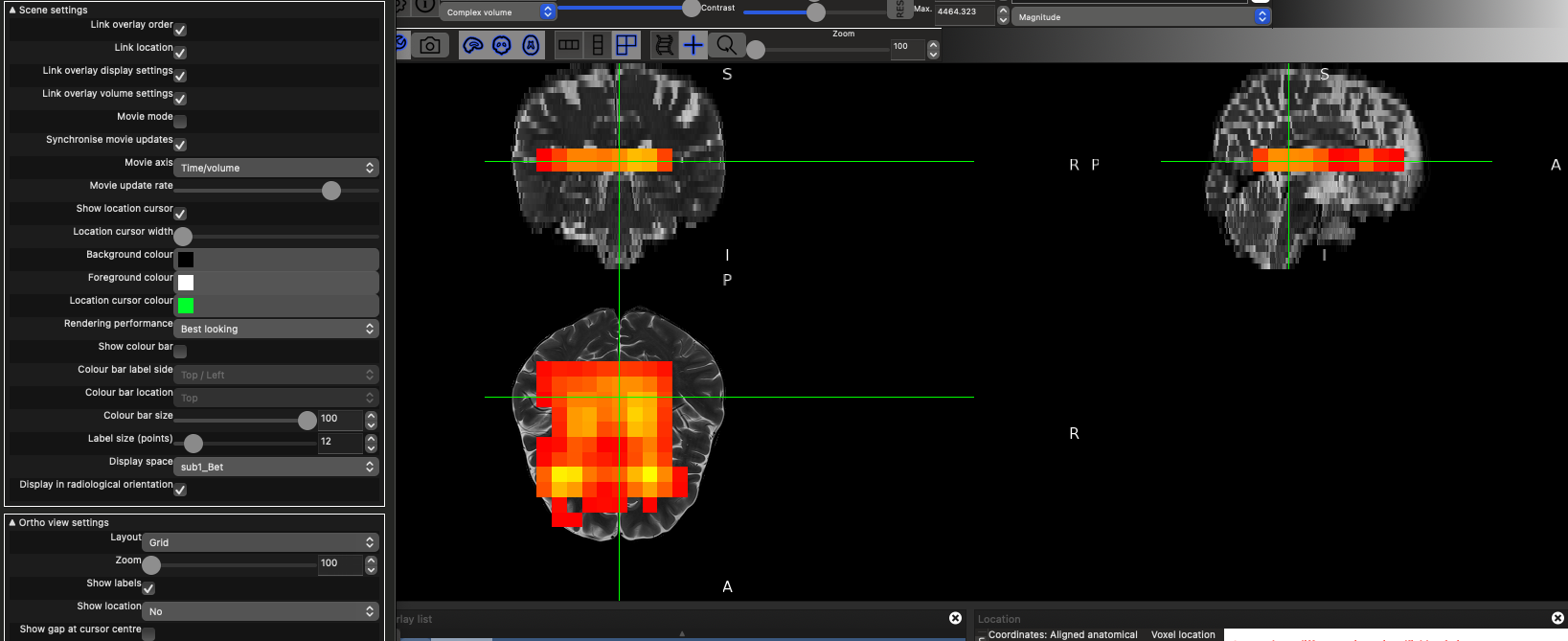
Actually @ardacanbas1 I think spec2nii might be doing the right thing anyway. The reason it appears with no orientation, is that you are viewing the data in the frame of the structural image, which has a rotation and to which the MRSI is somewhat matched to.
This is the data viewed in the World coordinates Display space (which is aligned with the scanner’s gradient frame)
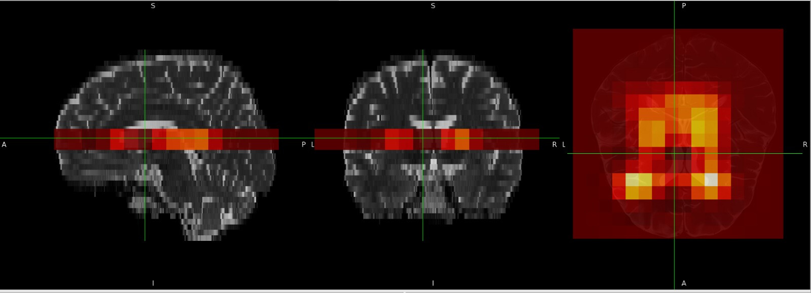
where an orientation is obvious. When we switch to the structural image sub1_Bet space with the same data, we see most of the orientation disappear in both:
The latter is what gets selected automatically when fsleyes is loaded (otherwise you see the tearing apparent in the first view). You can change it by finding the Display Space option in the ortho view View Settings menu look for the
in the top left.
Note there looks to be an AP/LR shift in the data but I think that’s because of the CSDE of the water residual, which is the dominant signal
Oh I understand now, and it is great to see the voxel box in the correct orientation
Maybe I should use your rotation approach in my code. I wonder what differs between our implementations. I will try to adapt it. Thank you !
I would really recommend not reimplementing everything. It took a long time to validate the orientation code in spec2nii. We did it so that you don’t have to
The thing is, my code is part of the Oryx-MRSI tool, and I’m currently trying to implement .rda data processing. That’s why I need to write your approach into MATLAB and then integrate it into my code, of course if that’s not a problem for you
However, have you considered calling spec2nii from Oryx and then load nifti. The idea of spec2nii was we all put effort into one location to be able to reliably convert disparate data types to a standard. Then we don’t all have to write our own (often incomplete) implementations.
Hello everyone,
Were there any problems with the alignment conversion in CoRegistration Error in Osprey with NIfTI? It didn’t take a long time to validate that code, as I only had the example of @meggon. I am still working with VE11E (upgrade is planned).
I used your code since @meggon’s data and mine share the same headers. It generated the voxel box correctly (except that I replaced PositionVector with the MidSlabPosition values), but the orientations were inverted, as shown in the screenshots above.
On the other hand, @wclarke’s spec2nii code seems to create voxel boxes with the correct orientation. I’m trying to understand what differs between the two approaches, since both use the same header entries.
It also seems that my data is VE11, but strangely it contains headers in XA format.