One common artifact that we see in MR spectra are unwanted water echoes. The spectrum below shows this behavior around 4 ppm. It manifests as a region of the spectrum with ‘locally increased noise’, which is more accurately considered as a broad signal with a large first-order phase error.
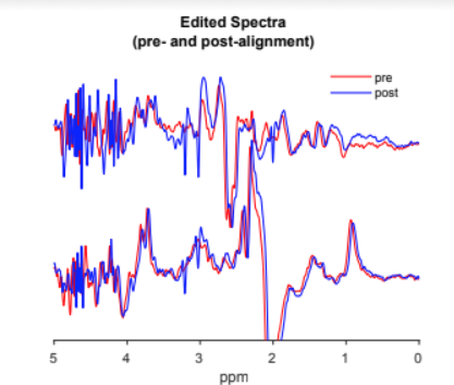
This happens when the sequence accidentally refocuses water signals from outside of voxel OOV (or merely fails to fully suppress them with the gradient pulses), and can seriously interfere with quantification. For a given brain location and acquisition protocol, these artifacts are relatively consistent and so can be ‘optimized away ‘. This process is something we advise collaborators to do every time they set up a protocol for a new brain region.
The key parameters are the voxel orientation (transverse/coronal/sagittal) which changes the ordering of the slice-selective pulses within the PRESS sequence (or rotates the experiment 90 degrees about a cube-face) and the water-fat shifts (L/R etc) which flip the slice-selective gradients one-by-one (reflecting the experiment spatially a plane parallel to a cube-face).
Before you work on a challenging brain region, make sure your sequence works in PCC or some other ‘easy’ region with which you have experience. When you are sure the sequence is set up correctly, then you can move onto this geometric optimization.
Step 1: Run an in vivo scan in a new brain region. Use 320 averages and ~25ml volume so you know what to expect in terms of SNR. If the spectrum looks ‘clean’ with respect to these OOV echoes, then I would not continue with this process. Run a new subject and hopefully that’ll look fine too.
Step 2: If you see OOV echoes, run scans with all three options of the orientation parameter, and select the one that gives the smallest OOV echoes.
Step 3: With that orientation, start working on the water-fate shifts. One quick option is to flip all three and see if it solves your problem. Hopefully you can see the OOV echoes in the Spectroscopy tool on the scanner. For each water-fat axis, select the option that gives the smallest OOV echoes.
This process is not 100% reproducible across subjects, but it is enough to be useful.
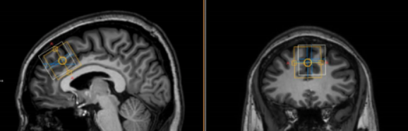
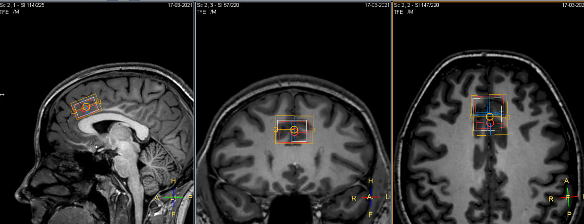
One final note: The data above were acquired from this midline ACC voxel. The orange box corresponds to the 3 ppm signal and the white to the chemical-shift-displaced water signal. When setting up a new voxel location, I tend to recommend setting the water-fat shifts to put the white box ‘inside‘ the orange box. By ‘inside’, I mean away from scalp and other challenging areas… towards the middle of the brain….
Cheeky cross-post from: Optimizing Voxel geometry on the Philips platform — Gannet